This tech note describes the process to interface and configure a flowmeter with the Rapidlogger System.
Flowmeters come in various types including turbine, magnetic (magflow), ultrasonic, Coriolis, and others. Most flowmeters provide a frequency-type output signal for interfacing with a totalizer or external data acquisition system. The Rapidlogger uses this frequency output to measure and record flow rate.
Coriolis, magflow, and ultrasonic flowmeters generate a square wave frequency signal using internal electronics. The output is typically an active square wave with a separate power supply, signal, and ground connection. This signal is directly compatible with the Rapidlogger frequency input.
Turbine flowmeters use a sensor fitted near a rotating impeller or propeller. As the impeller spins with the flow its blades pass near the sensor generating a frequency signal proportional to flow rate. Turbine flowmeters are available with different output types:
WARNING: The Rapidlogger does not support 2-wire passive magnetic pickup (sine wave) outputs. If your turbine flowmeter uses a 2-wire mag pickup a signal conditioner must be used to convert the sine wave to a square wave before connecting to the Rapidlogger.
All flowmeters provide a K-factor (also called calibration factor or flow factor) for converting the measured frequency to a flow rate. This factor is specific to each flowmeter and is typically expressed as:
The K-factor is usually found on a tag or label attached to the flowmeter body or on the calibration certificate supplied with the unit.
NOTE: Always use the K-factor specific to the flowmeter being installed. Do not substitute a generic value.
Connect the flowmeter frequency output signal to the Rapidlogger as follows:
| Flowmeter Terminal | Rapidlogger Terminal |
|---|---|
| Signal Output (+) | J5-3 (Frequency Input 3) |
| Ground / 0V | J5 Ground terminal (adjacent to J5-3) |
| Power Supply | Separate supply per flowmeter specification (do NOT power from Rapidlogger) |
NOTE: Refer to the Rapidlogger wiring diagram for the exact J5 terminal block location and pinout on your specific unit.
The Rapidlogger multiplier converts the raw frequency (Hz) measured at the input into engineering units. To display flow rate in barrels per minute (BPM) calculate the multiplier as follows.
If K-Factor is in Pulses per US Gallon:
There are 60 seconds per minute and 42 US gallons per oil-field barrel therefore:
Multiplier = 60 / 42 / K-factor
Or equivalently: Multiplier = 1.4286 / K-factor
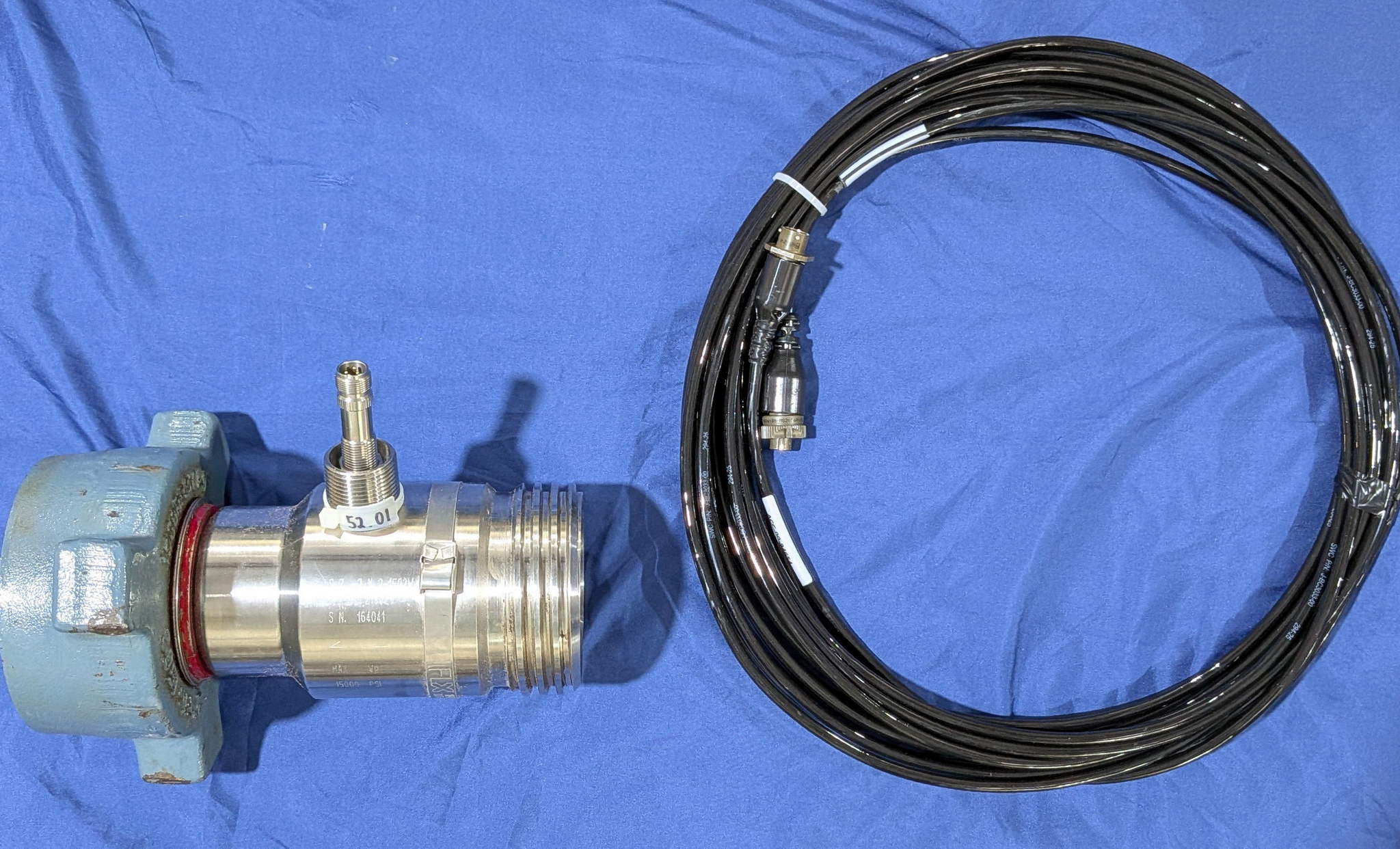
Example (K-factor = 52.01 pulses per US gallon):
Multiplier = 60 / 42 / 52.01 = 0.02746724
Enter the calculated value in the Multiplier field in the Rapidlogger System Utility.
If K-Factor is in Pulses per Barrel:
Multiplier = 60 / K-factor
Once the multiplier has been calculated use the Rapidlogger System Utility to configure the flow rate variable. Version 4.1.40 or newer of the Rapidlogger System Utility is required.
| Field | Setting |
|---|---|
| Variable Type | Frequency |
| Input Number | 3 (Frequency Input 3 / J5-3) |
| Units | BPM (Barrels Per Minute) |
| Multiplier | Calculated value from Section 4 |
| Offset | 0 |
NOTE: Save the variable file to your PC using the 'Write Vars File' button before and after making changes. This allows recovery of settings if needed. See Tech Note #13 for details.
In addition to flow rate a volume totalizer variable can be configured to accumulate the total volume in barrels. The Rapidlogger counts the total number of pulses received on the frequency input and applies a multiplier to convert to volume.
Totalizer Multiplier Calculation:
If K-Factor is in Pulses per US Gallon:
Totalizer Multiplier = 1 / 42 / K-factor
If K-Factor is in Pulses per Barrel:
Totalizer Multiplier = 1 / K-factor
Example (K-factor = 52.01 pulses per US gallon):
Totalizer Multiplier = 1 / 42 / 52.01 = 0.000458
In the Rapidlogger System Utility add or locate the volume variable and set the following fields:
| Field | Setting |
|---|---|
| Variable Type | Total (Frequency Total / Pulse Counter) |
| Input Number | 3 (Frequency Input 3 / J5-3) |
| Units | BBL (Barrels) |
| Multiplier | Calculated totalizer value from above |
| Offset | 0 |
Click 'Write All to Unit' to apply the configuration.